Raspberry Pi Garage Door Opener with GaragePi
Introduction
When I was little, I used to push the garage door button from inside the garage and then run out the garage while it's closing... carefully jumping over the sensor so I don't trip the safety mechanism. It was easy back then and a little fun. But nowadays, not so much. There are times when I wish I had a way to close (and open) the garage door remotely and preferably with something I always have on me... my mobile phone!
So this past Christmas, I looked into building something so I could use my smartphone as a garage door opener. I've read about the Arduino and Raspberry Pi platforms before that I believed would accomplish the task and, ultimately, I decided on the Raspberry Pi. The Arduino platform after some research and cost analysis would have cost more than the Raspberry Pi! That wasn't something I was expecting since the Raspberry Pi is more robust and a full-blown mini-Linux computer. The possibilities are really endless.
A wifi Raspberry Pi connected to a 2-channel relay connected to my actual garage door remote allows me to open and close my garage door with just a browser on my smartphone.
After only writing software for many years in web development, creating something that interacts with the real world was a special kind of excitement for me when I saw it work for the first time.
Below I'll go through the steps and the issues I ran into while working on this project.
Step 1 - Parts
Below is a list of the parts I gathered together to get started. Prices will most likely not be same.
- CanaKit Raspberry Pi 3 with 2.5A Micro USB Power Supply (UL Listed) - $47
- a 2-channel relay - $8
- female-to-female jumper wires - $8
- ethernet cable
- a LED to test out the GPIO pins
- solder gun + solder (if hooking it up to a garage door remote)
- usb keyboard and mouse, HDMI monitor and HDMI cable. These are only necessary for the initial setup until you have the Pi networked after which you can go headless and SSH in from another computer.
Total cost: $63 since I had a few of the needed parts already.
Step 2 - Setup the SD card
I followed this guide to setup the SD card with NOOBS and bootup the Pi for initial setup.
Raspberry Pi Quick Start Guide
Step 3 - Setup the Pi and Install Raspbian
Setting up the Pi is pretty easy. Just hookup the HDMI cable, usb keyboard and mouse, plug in the SD card prepared in step 2, and finally turn on the Pi by plugging in the micro-USB power supply. This should bootup NOOBS and step you through the process to install an OS. The one you want for this project is Raspbian. Complete the Raspbian setup and you should have a working Pi at the end.
It's at this step that I encountered my first problem. I used the keyboard and mouse I had from my main PC rig, a Logitech G110 keyboard and a Logitech G9 mouse. After NOOBS booted up, I found I couldn't type or control the mouse. The problem turned out to be the USB ports on the Pi doesn't provide enough power for the keyboard and mouse. You can get around this issue by using a powered USB hub.
Step 4 - Setting up Wifi
You can skip this step if you're going to leave the Pi connected with ethernet cable. In fact, I recommend skipping this step until the end to simplify things.
I didn't want the Pi to be tethered by an ethernet cable so I proceeded to try and set it up with the USB wifi dongle. This turned out to be probably the hardest part of the project. I followed a bunch of guides I found but none of them worked for me. It's not that the dongle wasn't supported by Raspbian, but I couldn't get it to connect to my wireless router. After much headache and tinkering around, I finally fixed the problem. You can read about the details in my wifi setup guide.
[update - 8/2/15] The new version of Raspbian includes a new version of a wifi manager that worked flawlessly for me and the above step wasn't necessary. Simply run the Raspbian GUI with startx then find the wifi manager icon in the upper-right corner and set it up for your wifi AP. Pretty straightforward with a GUI.
After using this setup for a few weeks, I found the Pi to be inaccessible after a period of inactivity. This turned out to be a power savings feature where the wifi component is turned off.
I did the following to disable this feature:
sudo vim /etc/modprobe.d/8192cu.confAdd the following:
# Disable power management
options 8192cu rtw_power_mgnt=0
Step 5 - Experiment with the GPIO on the Pi
What makes the Raspberry Pi so interesting to me are the GPIO pins which allow the Pi to communicate and control other peripherals. I found this excellent guide to get a basic understanding of the GPIO.
My first test with the pins was to simply connect a LED I had lying around and see if I could get it to light up.
LEDs generally have 1 leg which is longer than the other. The longer leg should be the + (positive) connection. If the LED doesn't have a visible difference in the leg lengths, then you can look at the top of the LED and you should see 2 small pieces of metal. The smaller side is the + connection. Here's a good diagram.
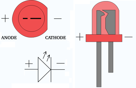
Start by connecting a jumper wire to GPIO pin 1 for the 3.3v power and another wire to the GND at pin 6. [photo]. This should light up the LED. Yay! Ok, admittedly, that's not terribly exciting. It's just a light.
Next, unplug the jumper wire from pin 1 and connect it to pin 7 which is GPIO4. The LED should be unlit for now. To control the GPIO ports, there are a ton of different choices. Just google for Raspberry Pi GPIO but I started with this wonderful framework called WebIOPi.
Follow the WebIOPi installation guide and run this:
$ sudo webiopi -d -c /etc/webiopi/configThat should start the webiopi server on port 8000. You can then access the webiopi page in a browser at http://192.168.1.60:8000. Of course, replace 192.168.1.60 with the IP of your Pi.
You should see a GPIO Header link on the main page. Click that link and you will be able to control the GPIO using a web UI which looks like the board header.

Click the 'IN' box to the left of GPIO4 to toggle that to say 'OUT'. Then try clicking on the box to the right of GPIO4 with the number 7 in it. If everything's working then you should now be able to on/off the connected LED.
Toggling the LED on/off was super exciting for me. It was the first time I had built anything on a computer that could interact with the real world. The Internet of Things as they say. For better or worse, it's coming and probably sooner rather than later.
Step 6 - Wiring the 2-Channel Relay
Now it's time to replace the LED with the relay. Remove the LED from the jumper wires and reconnect the wires according to this drawing below.

It was at this point that ran into my next problem. Every time I connected the relay and switched GPIO4 to 'OUT', the Raspberry Pi would crash and I'd have to unplug/reboot it. It took me awhile to figure out that the power supply I was using wasn't supplying enough power for everything. Apparently, powering the relay pushed it over the edge. The power supply I was using was from an old Motorola smartphone that was rated to only output 750ma. After I switched that out to another power supply I had lying around with 1850ma, I no longer had stability issues with the Pi.
You can test your connections now by going back to the WebIOPi page and toggle GPIO4 on/off and you should be able to see a small light on the relay respond accordingly. If you do, then that's a good sign. It means you are able to control the relay to open and complete a circuit.
Step 7 - Connecting to Garage Door Remote
For this step, you can either run wires to the actual garage door opener button that's in your garage, or use a spare garage door remote. Since I planned on leaving the Pi indoors where I have easy access to it, I chose to hook it up to a remote. I pried open the remote casing and studied the circuit board a bit. The first thing I did was to test if I could activate the remote without actually pressing the button so I shorted these 2 points by touching them with a wire.
Voila!
I heard the sounds of the garage door creaking open. So, theoretically, I should be able to wire that to the relay and have the relay open/close the circuit. Boistered by this knowledge, I looked at how I could solder 2 wires to the circuit and noticed that the remote was gracious enough to leave some extra holes that runs in serial with the actual button. Then I soldered 2 wires to the remote and connected them to the left and middle connections on the relay like this below.

Now toggling GPIO4 in WebIOPi should actually open and close your actual garage door. You might notice when you're doing this that the garage door only activates when the signal from GPIO4 is off. The relay I bought, the Sainsmart 2-Channel Relay and if what I've read is correct, most other relays work like this. When the signal is ON, the relay is open which means the remote won't activate. When the signal is OFF, then the relay is closed and the circuit is complete which should activate the remote. Keep this bit of info in mind when we work with setting up the WebIOPi code later.
Step 8 - GaragePi Setup
** UPDATE (2/17/15): Take a look at Node-GaragePi if you prefer Node.js to Python and how you can replace the battery in the garage remote. **
GaragePi is built using the WebIOPi framework by Eric @ trouch.com. It is setup with this file structure below:
pi@raspberrypi ~ $ tree garagepi
garagepi
├── config
├── html
│   └── index.html
└── python
    └── garagepi.py
Download and extract the GaragePi zip file to /home/pi/garagepi.
Or you can also clone it from Github:
git clone https://github.com/chasechou/GaragePi.git /home/pi/garagepiWebIOPi by default is setup with a login and password. But I only plan on using this when I'm on my local wifi network so I opted to remove the password protection completely. You do this by removing /etc/webiopi/passwd or empty it, then restart the webiopi server.
sudo rm /etc/webiopi/passwdRun this command below to load up webiopi with the new config file:
sudo webiopi -d -c /home/pi/garagepi/configThen load this up in your browser... again, change the IP to the IP of your Pi:
http://192.168.1.60:8000You should see a simple page like this below, please feel free to dress up the page however you want.

Clicking the button on this page should act as if you were pushing the button on your garage door remote.
If that worked, then you can make GaragePi run at startup.
sudo update-rc.d webiopi defaults

# As a side note, you can start/stop the background service by doing:
$ sudo /etc/init.d/webiopi start
$ sudo /etc/init.d/webiopi stop
Then replace the default config file at /etc/webiopi/config with a symlink to the config file at /home/pi/garagepi/config.
sudo rm /etc/webiopi/config
sudo ln -s /home/pi/garagepi/config /etc/webiopi/config
Reboot and test it out.
sudo rebootStep 9 - Save to Homescreen on Your Smartphone
I recommend you then save this page on the home screen of your smartphone, or at least bookmark it. Instructions for Android / iOS.

Have fun and hope it works for you!
Written by Chase Chou
Related protips
32 Responses

Cool One quick Q: the github code repo seems to have only the html index file and the WebIOPi config file. There's no python code at all - is this correct?
thanks for clarifying.

@berwick, that's correct. You need to install webiopi as mentioned in step 5.
Thanks. The reason I asked is that, at least in the config file I downloaded just a bit ago, the line in the [Scripts] section that points to a python script is not commented out with #.
It points to a (missing) python.py script in the garagepi dir. So if one fires up webiopi with that, it fails & raises a 'file not found' python exception.
I have to comment that out to get it to run.
Oops. Sorry I misunderstood your issue. Please either redownload the zip file or git pull from repo. The python script for garagepi was indeed missing!!
Thanks for pointing this out!
Hi, thanks! Yes, this did the trick. Thanks again for such a quick reply.
So one more question: it seems that when all this is in place and is working (as it is on my pi right now), then what happens for me at least is that at boot time, the Sainsmart 2 channel relay gets power from pin 4, and clicks 'on' (the red led lights up)
So - I guess depending whether the relay is normally open (NO) or normally closed (NC), then this might have the unexpected effect of opening the garage door every time the pi boots.... no? There ought to be something to deal with power glitches, I guess, as well....
thanks for any tips
berwick, I think I had that issue in the beginning before I added this to the config:
[GPIO]
Initialize following GPIOs with given function and optional value
This is used during WebIOPi start process
4 = OUT 1

Is the relay really necessary here? You could connect the remote directly to the pins of the pi, right?

🔴★ This is cool but you can do this cheaper and much easier with iHued cable. Cable basically connects your old $10 absolute android phone to you garage. You can open/close the garage vie web, and it also uses the camera in the obsolete phone so you see the garage open/close in real time like a webcam. Look http://www.iHued.com
@drio, I thought so too but I couldn't get that to work.

When I write sudo ln -s /home/pi/garagepi/config /etc/webiopi/config script, it says: ln: failed to create symbolic link : operation permitted or something (different language
@jussikoponen, i'm not sure what the issue is without more specific details. Maybe if you copy and paste what you see exactly would help.

@drio, @chase: you can connect the RPi GPIO to the base of an NPN transistor with the collector and emitter each connected to opposite sides of the garage door opener button. I've tested successfully following the Adafruit tutorial, which is nearly identical.

This is awesome! Thank you for the great tutorial. Is there a way to hook the pi up to the actual garage door opener instead of the button or the remote?
@dmikester1, yes it should be as easy as connecting the wires from the relay to the actual garage door opener... mine has 3 terminals and I believe it would be just connecting it to terminals 1 and 2. I haven't tested it out though but it's certainly possible.

Is it possible to use the power from the Pi to power the remote control circuit board and eliminate the need for the battery?

Hello @chase, not sure if you are still responding to comments for this post but I first wanted to say thank you for writing up this detailed walk through. After looking at a ton of different ways to control a garage door with a raspberry pi I settled on your method as it is super simple. I also have one question for you to if your willing. After I got everything all set up and I run top on my pi it is running around 99% and if I kill the webiopi garage door the cpu settles back down. I noticed in the Adafruit tutorial they have some code in the python script that says:
gives CPU some time before looping again
webiopi.sleep(1)
I don't see this in your code, is this something that can be added to help with the cpu load?
@davidbforbes, yes, in fact that is what I did in a later update since I found I had to change the battery every couple months or so. My garage door remote uses the CR2032 battery which is 3.3V and, coincidentally, the Raspberry Pi also has a 3V terminal which is right next to the 5V plug. So you basically remove the battery on the remote and connect the + on the battery compartment on the remote to the 3V on the Pi. Then another wire for the - to a ground on the Pi. Done!
@loral, I don't believe I had that issue with high CPU load. You can certainly try adding the sleep and see if it helps.
However, I actually rewrote the app using Node.js... if you're familiar with Node.js you are free to try it and see if it's better for you. I also connected a camera module and have the Node.js app taking a photo periodically and using that as the background on the html page.
You can check out node-garagepi at:
https://github.com/chasechou/node-garagepi
I hope to get some time to update my guide soon.
I actually have the same remote you are working with Chase. I however have connected the 3VDC from the Pi to the remote with a ground. It still does not seem to function unless I provide a CR2032 to the remote. I did verify that the 3VDC source from the Pi is connected to the positive terminal of the battery. I connected the remote to the pi and tried to manually activate the remote and I am still not able to get a positive result. Did you have to replace the battery even with the Pi power?
@davidbforbes, it works fine for me if I just connect the 3V power from the Pi to the remote and a ground. I no longer use a battery in my setup. Just double check you connected the 3V to the part that touches the top/side of the battery holder and the ground should be connected to the part that touches the bottom of the battery.

Hi @chase_chou - When I turn on my Pi and it gets to the log on stage, GPIO4 goes high and stays high. I've checked and in the config file I've got 4 = OUT 1. When I go to the webpage garagepi works fine, but the problem is that if I lose power and the Pi is turned back on, the pin will stay high until such time as you go to the webpage and hit the garage button. Any ideas on how to make GPIO4 stay low at startup? Thanks, Terry
@terrym86, try changing it to 4 = OUT 0
Hi @chase_chou, thanks that did the trick. Works great now on start up. However I notice when the pi is shutting down or going into reboot the gpio goes high for about 1s then low again. Is there a way to stop the gpio going high on shutdown or reboot? Thanks, Terry

Hi @chase_chou,
Your tutorial is too good. I have small doubt, as I want send the signal to a servo motor to rotate clock and anti-clockwise when the garage door is opened and closed respectively.
Can you help me with this, where should I add the servo motor program.
Thank you

I love the web page component. Very cool. Much prettier than anything I could build.
I built one using SMS. So I get a text when the door opens, and I can ask the door if it is open or closed, and open or close the door via SMS. Not as pretty as the webpage, but I like the proactive messaging. I also have it set to tell me if the door is open more than 30 mins or after 10pm. And I added a light sensor to tell me if the lights were on more than 30 mins (kids leave door open and light on frequently).
@ifermon, it sounds like you have a very interesting setup. What do you use to check if the garage door is open or closed automatically? I rely on seeing the actual photo since I added the camera module to the Pi.
For the garage I use a simple reed switch. The kind that they use on alarm systems to see if a window is opened or closed. Dead simple and $4 at your local hardware store. See link below. It lets you know that it's in a closed date or not closed state (which is different from opened, it could be partially opened).
I use a light sensor to tell if the lights are on. It only works at night, but that's part of the logic I set up.
I use Plivo for the SMS service. It's a pay service, but security is great and it's super cheap. I put in $20 to start the account and 6 months later of multiple SMS messages per day I'm still at $19 and change.
Link to light sensor:
Thanks for this article. Works perfectly with my setup. I did have a question on connecting the 2nd relay to control the 2nd garage door. Any insight on wiring that would help me immensely. Thanks.
im able to control the opener when connected to my home wifi, but not out on cellular data. I also don't get the simple garage door button when typing in the web address. what am i missing?
@Truckie you can do this by punching a hole through your firewall, but then anyone who hits the IP and port can control your door, so not really recommended. Other option is to set up username and password to login to your web build, but not really convenient. You could use VPN (something like OpenVPN) for quick access to your network, and it is the most secure option. One click and it will be just like you are on your wifi network. I would not recommend setting up your system to do this however, and you do so at your own risk. You are operating the largest/heaviest device in your home without being able to watch it. These doors have the power to cause severe property damage and harm or even death to people/pets/kids etc. Remote operation when not in view of the door is dangerous, and you are putting yourself in a very liable position doing so. Just something to keep in mind.
Have a fresh tip? Share with Coderwall community!